Presentation
For quite a long time, I am thinking about making a photography programmable remote for my DSLR camera Canon 450D (reflex). This remote should have a simple remote mode and an intervalometer mode (or Time Lapse mode). In this latter mode, the user just have to set the time interval between each photo and the remote will automatically shoot at this frequency. When assembling photos one after the other, you get a kind of video clip. Time lapse mode is mainly used to present long action in few second such as the life of a flower, the melting down of snow, cloud movement in the sky, etc ...
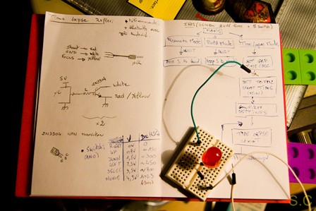
Interface with the camera can be made with an IR LED (if your camera got an IR receiver, lucky you!), or second option (easiest) with a jack cable plugged on the remote port of your camera. Cable connexion can change according to the camera model, but in most of cases, there are 3 wires: 1 wire for common, 1 wire for the focus and 1 wire for the shoot. So, you just have to short circuit the common wire with the focus and/or with the shoot one. That is all !
To control these connexions with some electronics, it is possible to use relays or transistors. Relays are safer than transistor thanks to the voltage isolation between electronics and camera. However, transistors are cheaper and smaller, that is why I chose this solution. To simplify electronics, I wired the focus and the shoot cable together. This mean I will not be able to control the focus independently. But it doesn't matter because I prefere to set manually the focus directly from my camera before starting shoot.
Hardware
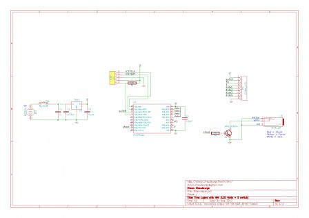
Now let's talk about input commands. To set the time interval, it is possible to use some potentiometers and on/off switch. We could imagine a simple electonics with few resistors, capa, potentiometers and a NE555 to generate a signal with a specific frequency. In this project, I wanted something more complete, with different modes and an important range of use for Time Lapse (understand an important range of frequencies). That leads me to choose a solution with a microcontroller and a small LCD screen (it is more "friendly-user" than potentiometer and switch !). After selected the components, I design the following simple schematic:
Bill of materials:
- 1 uC 16f690 : Free (thanks to MicroChip samples)
- 1 Pickit2 (or other programmer) : ~20€ (already got for previous project)
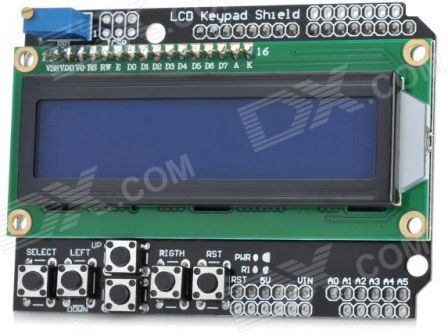
- 1 shield with LCD HD44780 2*16char and 5 buttons : 8€ (available on DX.com)
- 1 NPN transistor (2N3904) : ~0.3€
- 1 voltage regulator (LM7805) : ~0.6€
- some resistors and capacitors : ~1€
- 1 drilled proto-board : ~0.5€ (ebay)
- 1 Battery 9V: 1€
- 1 Battery clip: ~0.5€
- 1 Switch: ~0.5€
For the LCD, I chose a chinese copy of an LCD shield for Arduino. It is cheap and easy to use (no worries about contrast potentiometer for exemple, which is always a source of problems). The LCD is slodered in 4Bits mode, which mean only 7 pins are requiered to controll it (4 data + RS + Vcc + GND). Some links to understand how to use LCD in 4 bits mode:
link1,
link2,
link3.
In addition of the LCD, the shiled has 5 boutons (left, right, up, down, select). These buttons are in serial, and realize a voltage divider depending of which button is pressed. This means that, by connecting the buttons pin to an ADC of the microcontroller, we got 5 buttons which need only one pin of the microcontroller. Finally, the shield also has an hardware Reset button.
Solder it !
Once you got all components, it's time to solder all the thinks !
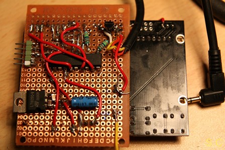
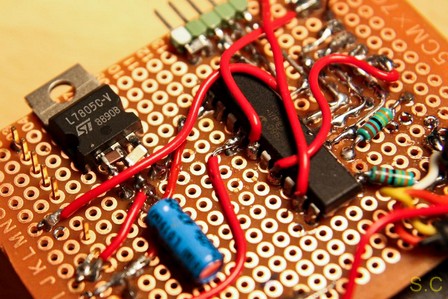
Because this project is just a protoype, I did not want to design a real PCB. Instead of that, as use wire wrapping technics to get quick results.
Software
Concerning the software, I used MpLab 8.86 and the compiler Hi-TECH PICC to program a small 8bits microcontroller (16f690). I use the free version of the compiler so the code optimisation is not available. This is why the software finally fill near the all flash space (4Kword) of the micro (and also because I wrote an heavy duty function with dirty multiplication and division to convert long number to a string (not proud of that :) ).
I coded two different usage modes: the remote mode and the TimeLapse mode.
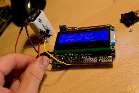
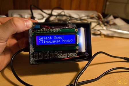
- The remote mode: use it as a simple remote for camera. Press the SELECT button to shoot. Escape the mode to the main menu with LEFT or RIGHT button. It is also possible to use this mode when your camera is in "Bulb mode" with a "shoot until press" function. This is very usefull to take pictures with an espacialy long exposition time, for exemple for "LightPainting", photos of storm, etc. Keep press the SELECT button to shoot. Release the button to stop the shoot.
- The TimeLapse mode: use it to automatically shoot with a defined interval (from 1 to 3600sec) during a defined delay (from 1 to 3600 min). The screen displays in real time the number of taken pictures. This mode automatically return to the main menu at the end of the delay or by pressing LEFT or RIGHT button.
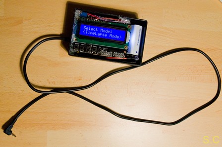
The final product in a (temporary) project case, and a video of how it works (in French):
About the autonomy
I measured a consumption of approximatively 40mA under 9V (360mW). So with a standard 9V battery (PP3) of 450mAH, I should be able to shoot during more than 11Hours. I good practice should have to desactivate the LCD after some time without push button (and switch the microcontroller into low power mode.
Making video clip
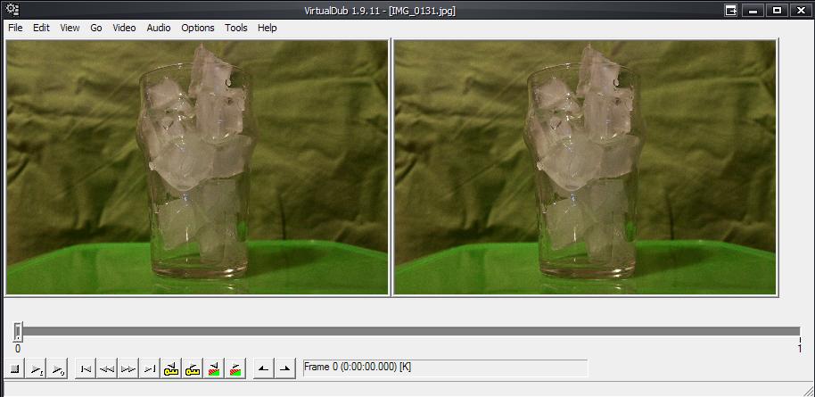
To convert all your photos into a video clip, use one of the lots of photos to video software. I tried some, but the only one I should advise you to try is the weel know VirtualDub. It is very easy to use for TimeLapse conversion and the advantage is that you totally control the video size, Bps, frame, codec, and other options. Have a look on this tutorial on timelapseblog.com
Here are some videos shot with my TimeLapse remote:
Conclusion
Finaly, I put the card with the battery in a plastic project box. For the future (soon, I hope), my goal is to design of cover for this box and print it with a 3D printer.
As a next step, I also project to add one or two step motors to slowly move the camera during time lapse shooting (camera glider). This will add a cool moving effect (have a look on some youtube videos). Adding motors means additional software code and as I fill all the Flash space of the 16f690, I will have to adapt the project for a bigger microcontroller...
Download
You can download
here the complete archive of this open source project.
Note for lazy people: If you are not enought patient to build a such remote, you can directly use a laptop with a time lapse software. Connect your camera to your computer and software will trig the photo shots. An other way, if you have a tablet, Ipad, Iphone or some other Android device, you can also use a TimeLapse Apps with an IR Led pluged on the jack audio output to control your camera.


